June
2, 2006
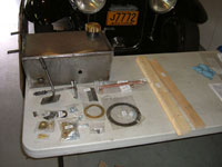
Kits 10 and 11 arrive. Check parts against the inventory list,
all accounted for. Note that the Floor Bracket #LK1720 is not
listed in the inventory but the attaching screws are.
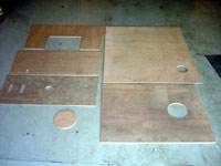
I pre fit the wood panels to see what would have to be
trimmed and measured accordingly.
1.5 Hours
June
3
Trim wood panels to fit. I had to make the inside diameter of
the Brass trim ring larger to clear the water tank neck. Sent
the fuel tank, step plates and several brackets to the powder
coater. I then polished the brass ring and fuel cap.
4.0 Hours
June
4
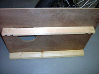
Assembly of the floorboards and cross supports, I glued and
screwed this assembly together using flush head construction
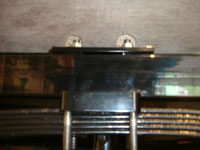
screws. Make sure you make relief's in the forward support to
clear the bolt heads on the chassis cross bar.
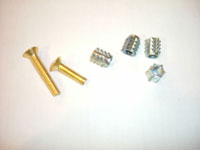
I decided to use nutserts in the floor board supports,
along with ¼ x20 brass oval head bolts to mount the floorboards
to the chassis. Since this board will be an access piece, it
goes with my design of having all panels easily removed and
installed for demonstration. The front floorboard cutouts for
the pedals had to be lengthened about ¾" on the
bottom end so the brake pedal would not be partially depressed.
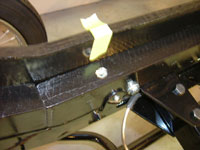
Also I had to cut reliefs in the bottom of this board where
the front spring mount bolts come up, so the floorboard will
rest on the floor supports not the spring bolts.
I purchased a small brass ring pull, like the 2 in the
kit, and installed it in the fuel access panel. I measured and
installed the pull rings and the latches for the front body
panel.
I drilled and retapped the brass assembly joints for
¼ x20 studs. I mounted the joints to the body side panels
with the screws and glue. Drilled my corresponding holes in
the back panel and mounted it to the body with brass finishing
washers and brass acorn nuts. (Same as I used for the body panels)
6.0 Hours
June
7
Dismantle the body panels and floor boards and prep for paint.
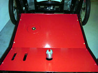
I primed all the boards both sides and painted them. I used
Black for the body panels and Red for the floorboards. This
took several days.
6.0 Hours
June 12
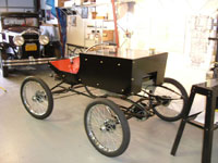
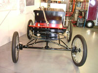
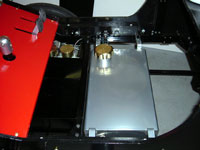
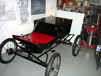
Install fuel tank and assemble all the components onto the painted
panels and floorboards.
Install on the car. I'm pleased with the progress.
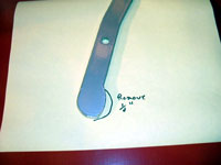
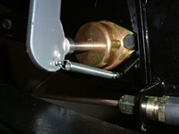
The brake pedal arm had to be trimmed where it contacts
the piston pin, because when the front spring is compressed
it hits the pedal and will cause the brake to slightly activate.
I trimmed about ¼" to obtain the clearance from
the spring. Also I fabricated a pedal retainer so it is always
in contact with the piston pin and not swinging freely about.
(Anti-rattling)
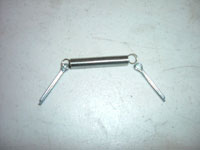
I used 2 cotter pins and a light spring. Drill a hole,
slightly larger than the cotter pin diameter, just below the
master cylinder in the pedal plinth and a hole in the pedal
horizontal with the brake pin. Install the spring onto the cotter
pins, insert cotter pins in the holes drilled and bend over
the pin tabs. The spring is just strong enough to hold the pedal
against the brake pin, but not strong enough to engage the master
cylinder
4.0 Hours
I found everything to fit rather well and trimming of the body
panels would be expected. I assembled Kit 11 before Kit 10 so
as not to have large panels taking up shop space. I'm going
to wait for the lubricator to show up before I modify the bracket.
Happy
Building;
Rick
Click
pictures to enlarge
Likamobile
Home • Kits
One and Two •
Kits
Three and Four • Kits
Four-B and Five •
Caliper Correction
Kits Six and Eight •
Kit
Seven • Kit
Eight • Kit
Nine •
Kit
Ten • Kit
Ten Addendum • Kit Eleven
Kit Twelve •
Kit
Thirteen • Kit Fourteen
• Kit Fifteen •
Year End • Kit
Sixteen • Leaf
Spring Modification
Kits Seventeen / Eighteen
• Engine
Modification • Boiler
Installation • Burner
Installation
Fuel Line, Brake &
Throttle Pedal Installation • Final
Kit • Final Assembly
& Steam Up
Road Test & Modifications
• Purge Modification
